
Recording tape technology developed rapidly during the second World War but its first major application in broadcasting came in the USA when Bing Crosby saw its potential for allowing the pre-recording of his popular radio programme so that it could be broadcast at the same hour in all the different time zones across that continent. Previously, one coast would hear the show in late afternoon while on the other coast it would be late evening. Naturally, the same problems existed with TV shows. Research in the early 1950s focused on developing a tape recording format for video of sufficient quality to allow both immediate and delayed playback, including the capacity to cope with colour which had been introduced in the USA in December 1953 using the NTSC standard.
In the USA the main players were RCA (which did much of the early pioneering work) and the Ampex Corporation, whose research team included Ray Dolby, whose name would go on to become synonymous with sound processing systems. In the meantime in the UK, the BBC was experimenting with VERA. The US machines produced by RCA and Ampex were similar to each other in principal, although there were differences in construction and circuitry detail.
The Ampex VR1000B and the RCA TRT1A used magnetic tape 2″ in diameter, 1.4 thousandths of an inch thick with a Mylar base, and stored on a 4800 foot reel. The tape ran at a linear velocity of 15″ per second, the same as for broadcast audio, and could record just over an hour of video. The tape manufactured in the 1950s and 60s was much less robust than nowadays and would deteriorate to the point of uselessness after only 100-200 tape passes (dependent on other factors such as storage, temperature, humidity etc.).
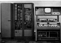 This photo shows the Ampex VR1000B, the first video recorder in world-wide commercial use. This model would have been used to record programmes such as Hancock’s Half Hour, A For Andromeda and early Doctor Who episodes. The two open equipment racks contain ancillary circuitry which could not be fitted into the body of the recorder. The third, closed, rack contains colour processing circuitry for use in the USA. | 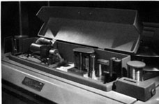 The tape path on the VR1000B. | 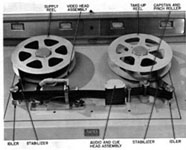 View of tape loaded on VR1000B. |
In order to record the full TV signal bandwidth of around 5MHz, a head to tape speed equivalent to 1500″ per second is required. This relative writing speed can be achieved by the tape running at 15ips past a drum containing four heads, placed at 90° intervals, rotating at 15000rpm (14,400rpm in the USA). The four head arrangement gave rise to the format’s name – Quadruplex.
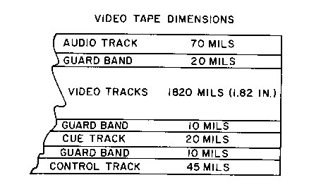
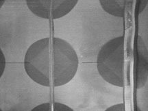
The video signals are recorded transversely across the width of the tape. with each head pass recording 16 lines (ie 64 lines recorded per rotation of the head drum assembly). A control track is recorded along the lower tape edge (the electronic equivalent of sprocket holes in a film) to allow synchronised replay of the recorded information. Originally, for monochrome recordings, these sync pulses were recorded at a frequency of 25Hz; with the introduction of colour recording in the mid 1960s they were recorded with a frequency of 12.5Hz to assist with identification of the correct colour phase. This was of use only for physical tape editing. When electronic editing started to become the norm sometime around 1968, it became preferable to identify the eight field PAL colour framing sequence to ensure a stable colour edit. Unfortunately, this remained something of a process of trial and error well into the 1970s. Also recorded on the tape are a Cue track (for timecode, or a further audio guide such as gallery instructions) and an Audio track. The pattern of signals recorded on the tape are illustrated below:
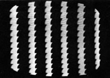
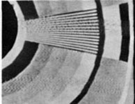
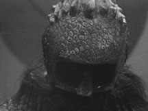
Head to tape contact is critical to ensure a good signal for reproduction. The tape is held firmly in position adjacent to the rotating heads by an assembly containing a vacuum, while compressed air is blown through the head drum assembly itself (helping to cool the system and blow away loose oxide/chips of tape loosened by the record and playback process). At the point of contact between the head tips and the tape there is a pressure of around 1000lb per square inch. Not surprisingly, therefore, the heads tend to stretch and distort the tape surface slightly. If during playback any part of the head arrangement or vacuum guide is incorrectly positioned relative to the recording process, the horizontal scan lines are reproduced with a characteristic pattern of distortion, due to the different degrees of tape stretching. The commonest patterns of error are shown here:
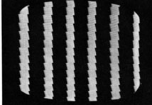 | This venetian blind type effect is due to the vacuum guide being positioned too close to the head tip, when compared to to recording process. |
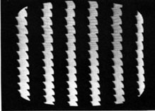
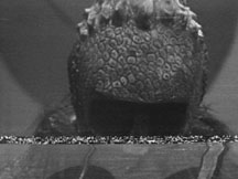
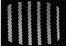 | Here, on playback the vacuum guide is positioned too far away from the head tip, compared with the recording process. |
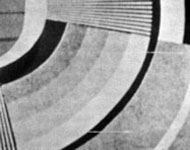
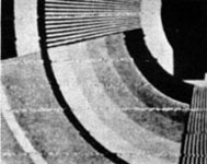
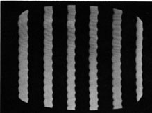 | This pattern of scalloping appears when the vacuum guide is positioned too high (vertically), when playing back a correctly-recorded tape. This accounts for the wobble visible on production credits seen on many film recordings from the 1950s and 60s, where the vertical movement of roller captions with high contrast text shows this error particularly well. |
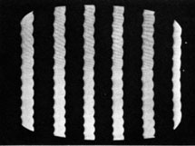 | The reverse type of scalloping occurs when the vacuum guide is set too low. |
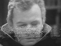
 | Here, the vacuum guide is set both too far from the head tip, and too high vertically. This is almost certainly the fault exhibited on the sequence at the beginning of the Doctor Who story “Tomb of the Cybermen”. As the serial was made on videotape, it seems likely that the scene was edited physically into the episode from a different recorder; consequently when playback was attempted for film recording, the characteristics of the two sections of tape would be different and the machine would have been calibrated for the bulk of the episode, and the automatic correction circuits were not used. See film recording page. |
 | Here, the vacuum guide is set too close to the head tips, and too low vertically. |
Normally, in playback, the time between sync pulses is measured and, if an error is present, a correcting voltage can be applied to a servo motor to move the vacuum shoe appropriately to correct the error. However, the latitude of the automatic system is fairly small and manual controls are also necessary to compensate for changes in temperature and humidity.
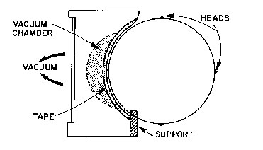
Cross-section of the vacuum guide/shoe for the 2″ Quad recorder.
Other playback problems manifest from time to time, giving characteristic appearances as follows:
The tape is scratched, causing (usually) dark lines in a geometric pattern (most often diagonal steps as the heads read their own 16 line segments).
Dropouts appear as white or dark lines. The cause is loss of contact between the heads and the tape oxide. This may be due to physical separation, a foreign body (dust) on the tape, or a section of missing oxide on the tape (common, given the fragility of early tape and the huge pressures exerted by the heads).![]()
Where the heads are transiently out of position with respect to the tape, mistracking occurs and there is a reduction in signal which can vary from a reduced signal:noise ratio, through mild moire patterning to a complete loss of picture.
Unwanted RF signals in the head electronics cause this characteristic zig-zag interference superimposed on the picture from a head sweep.
These are black or white lines occurring due to improper timing of the head-switching system. The artefactual signals should fall within the horizontal blanking period (ie the 10 microsecond period in which the electron beam returns to start a new horizontal scan line).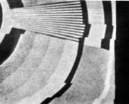
This is delay banding, caused either by differences in head geometry and/or differences in the electronic delay set between the different head channels. Here 3 heads are set correctly, the fourth’s line signal is clearly delayed excessively.
In colour recordings, timing errors caused by faulty head tip adjustment, vacuum guide setting or electronic delay line setting can result in more noticeable colour errors than geometric errors; commonly subtle (or not-so-subtle) hue errors occur in a characteristic pattern known as Quad Banding.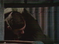
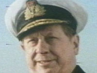
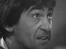
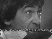
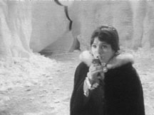
Not strictly speaking a tape reproduction error, but a picture fault nonetheless, is the phenomenon of microphony. Here, the critical alignment of the 3 colout tubes in a studio camera is upset for a time, often lasting several seconds, by the physical vibration effect of loud noises (in this case a prop gun firing blanks).
The minimising of this problem is one reason why many loud sound effects were added from disc or tape in the production gallery or, later, in post-production. It is also cited as one reason why pop groups were encouraged to mime on “Top of the Pops”, as opposed to playing live (loudly!). This phenomenon does not occur with chip cameras.
Dropouts were corrected in later Quad recorders to a degree by compensator circuits. These were analogue delay lines storing the previous line, which could be substituted into the signal if the FM signal sampled from the tape falls below a pre-determined level. This could hide small dropouts only.
From 1958 to 1968 exclusively (and afterwards to a lesser degree) Quad videotape was edited by being cut physically with razor blades and rejoined with redundant tape removed. This had implications of cost in that, once edited physically, tapes could not usually be erased and re-used for another programme. A BBC production office would have to take the cost of raw tape into account from its budget, and often it would be possible to use a previously used tape at a much lower cost to the budget.
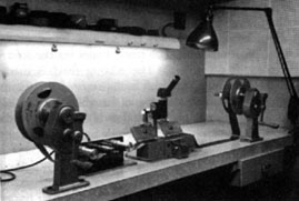
A typical 2″ tape editing bench, with tape reel holders, splicing block to ensure perfect opposition of tape sections to be edited together, and microscope to assist with accurate identification of sync pulses.
The tapes could not simply be cut randomly, as the picture would roll and the playback recorder would take several seconds to relock to the sync pulses. The videotape editor would have to identify the sync pulses on the edge of the tape using a solution of fine iron filings and a microscope. When the solution is painted onto the tape edge, the iron is drawn to the sync pulses which can then the visualised. The tape would then be marked with a chinagraph pencil and the iron solution wiped away. By knowing the position of the sync pulses the tape could be cut and rejoined during the vertical blanking period, thus ensuring a smooth cut without any picture disturbance. However, in the early 60s and before, it was not possible to identify fields and, not infrequently, small picture disturbances would occur with edits as recorders momentarily locked to the new sync.
 |  |  |
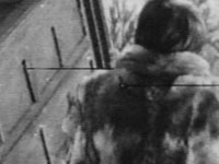
| Frame preceding edit point | In these examples, the physical edit is too early and the vertical interval information is visible followed by a distorted section from the next frame | The following frame is back to normal (note dropouts and also visible scalloping accentuated by the picture content). |
 |  |  |
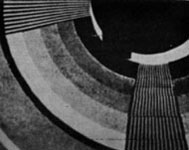
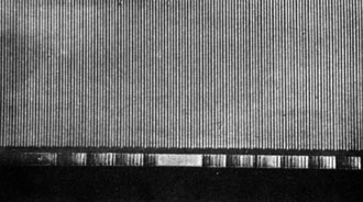 | This picture shows a quad tape “developed” with a suspension of iron, showing the transverse head sweeps and control track sync pulses. |
The first Doctor Who story to be recorded using Quad tape was the pilot episode version of An Unearthly Child. Episode 3 of The Enemy of the World was the first to be recorded on 625 lines and may well have been the first episode to be edited electronically (as opposed to physically) – although this is by no means certain. Doctor Who and the Silurians was the first story to be recorded and edited on video tape in colour. The last Doctor Who story to be recorded on 2″ Quad tape was The Five Doctors. In total the active working life of the Quad format was around 27 years – a record that is unlikely to be matched by any subsequent broadcast format.
Sources: Video Tape Recording, Julian L. Bernstein, Chapman & Hall, 1960; Video Techniques, Gordon White, Heinemann, 1988.