Between 1936, at the start of high definition television broadcasting in the UK, until the late 1940s there was no way of adequately recording a television signal. The few visual records existing are films made in TV studios while programmes were broadcast, but are not true recordings of those programmes.
Long before videotape existed, it was considered possible to record a TV programme from the output of a cathode ray tube onto celluloid film. In America the process was pioneered and perfected by William A. Palmer and was known as “kinescope recording”, while in the UK it was known as “telerecording” or “television film recording”. One of the first items to be film recorded in the UK was the Queen’s wedding in 1948. Even when videotape became commercially available in 1958, film recording continued to be used for recording programmes as a film copy was actually cheaper than a tape copy (raw 2″ quadruplex videotape tape stock was the equivalent of 2000 UKP per hour then, in today’s terms, and even major broadcasters like the BBC would have very few recorders as they cost the equivalent of hundreds of thousands of pounds). In addition, film recordings circumvented the problem of differing video line and field frequency standards around the world, making foreign sales of programmes possible.
It is often assumed that film recordings are poor in quality compared with the original video image. While this is sometimes the case, excellent recordings are possible and, certainly, will be more reliable for reproduction at the current time than 1950s stock video tapes, were many still to exist. For example, few 405 line Quad recorders exist, even fewer 405 to 625 line converters survive, and drop-out, off-locking due to lost sync, and other playback problems would, in many cases, render tapes unplayable or poorly reproducible.
The first Doctor Who episode to be film recorded was the pilot episode version of An Unearthly Child. The last to be recorded for foreign sale was episode 6 of The Green Death, although episode 1 of Invasion of the Dinosaurs exists as a film recording, and sections of Tom Baker episodes up to The Talons of Weng-Chiang were film recorded for inclusion in the film reel of Whose Doctor Who, the Lively Arts documentary from 1977.
The Basic IdeaIf one points a cine camera at a TV screen an image will be recorded, but a black bar will run up and down the picture due to the lack of synchronisation between the CRT (cathode ray tube) scanning lines and the camera shutter. This is well demonstrated by the uneven exposure on off-screen footage of Doctor Who taken in the late 1960s by an Australian fan.
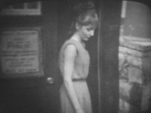 | 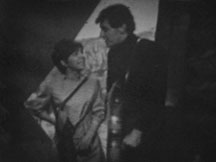 | 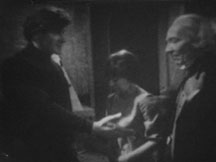 |
Kits were available for electronics buffs in the 1960s to modify 8mm cine cameras to lock the shutter rate to the same frequency as a TV set, with a motor phase adjustment to move the “black bar” out of the visible area; it is uncertain whether examples exist in private hands. Some years earlier, primitive recording techniques at the BBC used the same principle. However, further problems existed which needed to be solved to give good quality film recordings. These involved electronic, mechanical, optical and photographic aspects. These can be summarised as follows:
1 The Pulldown Problem
2 Synchronising the Camera and TV signal
3 Maintaining Good Gradation
4 Maintaining Good Resolution
5 Photographing an Interlaced Image
6 Movement Rendering
7 Grain and Noise
8 The Incoming Image
1 The Pulldown Problem
This was always the major problem in recording a TV image. In a normal cinema film, half of the 1/24th second frame period is used for exposure and half to pull down, settle and register the film in time to record the next image. Thus, around 20 milliseconds (msec) is available for pulldown.
However, a 405 line TV picture is actually made up of 377 active lines, traced by a single electron beam on a phosphor-coated cathode ray tube. Each picture element is flashed on the screen for an instant, then fades away. Furthermore, the image more truly consists of two interlaced fields of 188.5 lines each. There is only a blanking period of 1.4msec between each field during which no picture information is being drawn on the screen. A film pulldown with accurate registration at this speed was impossible in the 1950s and 1960s (a 35mm film would have to be accelerated at 4000G for 0.7msec, then decelerated at 4000G for another 0.7msec! 1600G would be required for 16mm film!! Even if such accelerations could have been achieved mechanically, the film would almost certainly have snapped or been damaged under the strain). To solve these problems, four systems were developed.
Suppressed Field
In this system, used during the 1950s and early 1960s, of the 50 fields per second in the original image, only alternate fields were recorded. The picture thus consisted of a maximum of 188.5 lines. 20msec was available for film pulldown and this simple arrangement gave surprisingly good results.

Stored Field
Here the camera lens was shuttered during alternate fields, giving 20msec for pulldown, but the lines written on the screen during the shuttered period were preserved as an afterglow in specially produced phosphor which retained brightness, so the two fields were on screen simultaneously. The “stored” field had to be pre-emphasised electronically so that, when it had decayed in brightness it matched the “live” field. Of course the situation was more complex, as the amount of pre-emphasis needed varied depending on the position of a line on the screen (the first line of the stored field was photographed after 20msec of decay, the bottom-most line after only 1.4msec). The same principles applied to lines in the “live” field. Thus, contrast and gain modulation of the incoming signal had to be varied continuously through a 2 field period. This modulation was applied to the CRT’s vision amplifier as a voltage, dependent on the phase of the camera shutter mechanism.
Partial Stored Field
Here a faster pull-down time of approximately 5msec was exploited (at the time, the fastest 35mm cameras could achieve), which meant that only 1/5 of an active field was displayed when the camera shutter was closed. Again, brightness and contrast had to be modulated to give equal exposure from different screen areas, but as most of both fields were exposed “live”, this was able to be achieved with a fixed neutral density filter over a portion of the display monitor.
Quick Pull-Down
Here, with this Marconi-developed 16mm camera, the pull-down time approached 1.4msec so no pre-emphasis or phosphor storage was required. More accurately, pull-down time was actually 2msec, so 12 lines per complete picture were sacrificed, ideally 3 lines from the top and bottom of each field. A disadvantage of the high-speed pull-down camera was that the braking mechanism could scratch the film emulsion, causing a gradual build-up of emusion which could further scratch, or cause unsteadiness in the film (especially with long running times of up to 60 minutes with 16mm film). By the mid 1970s, film recording apparatus was available for colour or monochrome recordings which could pull down in around 1.6msec.
It is not clear which method would have been used to record programmes such as Doctor Who in the 1960s; it is probable that quality and method of recordings would depend on random factors such as which Quad recorder, video channel and film recording apparatus was available at the time (the BBC had up to 20 film recording units at the system’s peak and these spanned all the above systems). It is likely that most, if not all, 16mm recordings were quick pull-down, with perhaps some early episodes partial stored field.
2 Synchronisation of Camera and Shutter
With suppressed field recording, shuttering and pull-down had to take place during the field suppression period. If not, a thin, light grey horizontal line (due to a duble exposure) or a dark band (due to under-exposure) would be visible. Also movement rendering would be affected if some lines were recorded from field A (upper, or dominant) and some from field B (lower or non-dominant).
With stored-field recording, a phase error would also lead to a horizontal banding effect with a 200 line structure, due to exposure imbalance between live and stored fields.
With partial stored-field recording, phase errors would also result in light or dark bands on the picture. This did occur with fast pull-down but tended to be restricted (unless gross) to the 12 lines sacrificed from the recorded image.
3 Gradation
The TV signal from a film recording was passed along a chain, from camera tube, via control unit, (sometimes vision mixer and possibly Quad VTR) to non-linear amplifier, to CRT, thence to film negative, optical printer, positive film and finally, telecine output. Any part of this chain introduced the potential for picture degradation. The contrast of video differs from film and different settings would be used depending on whether a print was destined to be telecined for transmission or shown optically in a theatre (for example, to servicemen abroad). Prints produced for projection tend to look poor on telecine, and vice versa; often “compromise” prints would be produced for maximum flexibility (see the examples below left, of low-contrast print destined for telecine and right, of high-contrast viewing print).
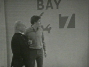 |  |
4 Resolution
Resolution, or sharpness, could also be affected at any of the signal chain. The first loss tended to occur at the phosphor of the CRT, where the beam could spread to adjacent phosphor (especially at the edge of highlights) and resulting flare could remove clarity from the picture – rather like looking through smeared spectacles or a diffusing filter. Horizontal resolution could be corrected to an extent by boosting the high frequencies of the signal before display, but vertical loss of resolution was a problem until the late 1960s. Of course, suppressed field recording involved the most major loss of vertical resolution (50%)! Further loss tended to occur during film printing, especially if done in a continuous motion printer, where any slight film slippage would cause vertical smearing and loss of resolution.
5 The Interlaced Image
In good CRT displays, the diameter of the scanning spot is less than the gap between adjacent lines, i.e. there is a strip of black between each line. If these lines were recorded on film, during projection the image would be reasonable. However, if the print were to be telecined, the reading scan lines would not exactly match the written lines and moire patterning would occur. This can be compounded on telecine transfer as (in the 60s) the film print would be underscanned by 3% in the fast pull-down system, and 377 lines would be created from 365 on the film. Nowadays, in the PAL system, 572 lines read from 365. To reduce the visibility of individual lines, spot wobble was developed. A high frequency (20MHz) alternating field was superimposed on the CRT spot beam, causing a small vertical strip of phosphor to be illuminated rather than a thin line. Hence, there should be no black between adjacent lines. Spot wobble was also used in the telecine transfer of film recordings, reducing further line structure but, again, at the expense of vertical resolution. Modern telecine apparatus does not have spot wobble facility, which can make replay of archive material difficult. However, the spot astigmatism controls can be adjusted to defocus the spot in the vertical direction to achieve a satisfactory result.

If the odd and even fields were not exactly and evenly spaced, pairing of lines could occur, again causing problems with patterning of dark and light stripes. With suppressed field recording, while there could be no interlace problem (as there is only one field), spot wobble adjustment was still critical to avoid strobing or moire patterning on reproduction. With stored field recording, any problem with registration of the fields would upset the modulation of brightness, leading to a visible 188 line structure and patterning. Partial stored field and fast pull-down were also both subject to similar problems, particularly if there was movement of the camera, or slippage of film in the gate.
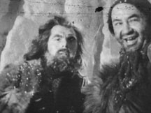 The black artefacts are due to physical damage on the film negative, almost certainly during recording, leading to “snagging” of the film in the recording apparatus. | 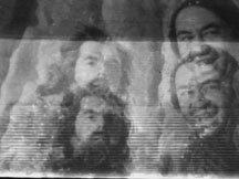 This causes misregistration on the next frame. The top section is underexposed (one field only), the middle is correctly exposed but with incorrect registration of fields; at the bottom is a 188 line structure. | 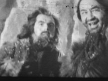 In the next frame, again some physical film damage is visible and the entire image has slight misregistration. The subsequent frame (not shown) is back to normal. |
6 Movement Rendering
Normally, with cinema film, each 1/24th second frame is displayed twice (to reduce visible flicker). To achieve this on TV each 1/50th sec field is displayed sequentially. When committed to a film recording, subsequent fields become “locked” together and, in reality, cannot be recovered independently (an “ideal” film recording reproduced on an “ideal” telecine could do this and the original smooth video-like image would be obtained. This theoretical possibility is, in fact, effectively impossible). In video, with 50 discrete images per second, movement rendering is twice as smooth as with film (including film recordings). This is what gives film and video different “looks” and the recent “filmising” technique (or at least the simplest variant of it) mimics the look of film by discarding alternate fields (thus halving vertical resolution akin to suppressed field recordings – “what goes around comes around”!!) and using higher than normal contrast lighting.
The different film recording techniques resulted in different characteristics and potential problems with recording movement.
With suppressed field recording, movement was reproduced accurately, but less smoothly, and gave a result similar to standard film.
Fast pull-down recordings had two consecutive fields recorded on one frame. If there was movement of a subject, there would be a difference in position of the images and a 188 line structure would be visible on moving edges (an similar artefact is produced by modern video capture cards in computers on rapid movement in images). With telecine reproduction, the movement rendering problem can be exacerbated as some lines originating from Field A in the original picture will be reproduced during Field B, and vice versa. Some parts of the picture may therefore have smooth motion while others have a jerky, strobing effect.
Partial stored field recordings suffered the same pitfalls, but could be made worse by artefacts from the long phosphor decay on the CRT, sometimes leading to trailing images on leading edges. Stored field recordings were worse still for these artefacts.
If telecine and recorder scans are out of step, movement rendering can be particularly bad, as each frame is an interlaced mixture of two video frames (originating from four fields). Certain picture elements can be up to 3 or 4 fields (or 1/12th sec) away from their true position in time. Worse still, if film inserts were part of the original tape and were out of phase, the effect could be doubled, with picture elements up to 1/6th second out of position. This problem arose on the film recording of Episode 6 of The Mind of Evil. Fortunately episode 5 contained the same footage without the phase error and the sequence could be substituted for the video release (for more details see the Mind of Evil page on Steve Roberts’ Restoration Website, or follow this link away from this site).
7 Grain and Noise
Three types of grain and noise can be apparent on film recordings.
Electrical noise, introduced at any stage of the signal path, is random and tends to be most visible in dark areas.
Photographic grain is also randomly distributed and is most visible in mid-tones. It is made worse by high gamma processing of negative film stock, which was done with most film recordings. This and electrical noise can be eliminated to some degree by temporal noise reduction techniques currently available (where a pixel is compared and, depending on chosen parameters, averaged with values of the same pixel in previous or subsequent frames), but often at the expense of some motion blur, which may be a more distracting artefact than the original noise!
Grain in the phosphor of the display CRT is most noticeable in light areas of the picture and, though random in distribution spatially, is static over time. The artefacts caused are particularly noticeable on panning or tracking shots and can be likened to looking through a dirty window. Temporal noise reduction will, if anything, emphasise this defect. Spatial noise reduction (averaging adjacent pixels in the same frame) can help, but at the expense of picture resolution.
Noise tends to be amplified somewhat with suppressed field recording in particular, as each scan line is effectively stretched vertically, with any noise stretched in proportion.
8 Incoming Faults
Garbage in, garbage out. Obviously any defects in the incoming signal, whether of brightness or contrast, noise or geometry, would be recorded. For example, vertical lines could slant; line velocity errors (usually due to incorrect adjustment of tape guide height during quad playback) manifest as zig-zag distortion especially noticeable on verticals; tape dropout could be recorded; excessive underscan would give a zoomed-in picture with loss of picture area and reduced resolution.
Because of the expense involved, only the most disastrous problems would result in a film recording being aborted. Consequently, many films have the above faults present at times.
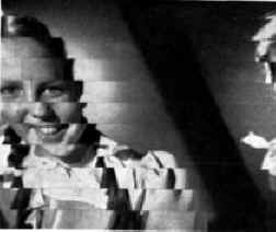 Line velocity error on a TV Set |  On a Quad Videotape reproduction, the error does not accumulate across the whole image but restarts with every head sweep across the tape. Note the distortion on vertical lines. This is especially noticeable on zooms or pans as a rippling effect. |
Further Developments
During the 1970s the techniques were refined further and modified to allow colour film recordings to be made. Independent TV companies and facilities companies used this more than the BBC, which increasingly used videotape with analogue (and subsequently digital) standards conversion for foreign sales by the mid 1970s. One interesting system, called Vidtronics colour separation, used a 35mm fast pulldown camera developed by Moy and the BBC where the red, green and blue components were each recorded on monochrome film in different passes, then subsequently combined in printing to make a colour internegative or positive print. Other systems used the same principle as partial stored field recordings, but with a special shutter to compensate for afterglow differences from a high grade colour monitor. A system called Trinoscope (or videoprinting) used CRT projectors for R, G and B combined into a fast pulldown camera via semi-silvered (or dichroic) mirrors. Direct electron beam recording onto film was developed in the mid 1970s, giving excellent results, and with digital frame store capabilities came the ability to fully interlace an image which could be recorded by a fairly standard camera (in effect a digital stored field system). Further discussion of these systems is beyond the scope of this site.
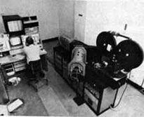 Trinoscope Recorder | 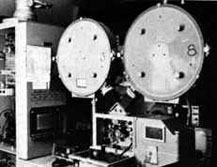 16mm Film Recorder | 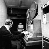 35mm Film Recorder |
Various sources have been used in the preparation of this page. Particularly of note are the following: “The Technical Problems of Television Film Recording” by A.B.Palmer, Journal of SMPTE, Vol 74, Dec 1965, “Television’s Story & Challenge” by Derek Horton, Harrap & Co Ltd, 1951, “Practical Television” by T.J.Morgan, Ward Lock & Co Ltd, 1959, “Recording Colour Television on Film” by Angus Robertson, Video & Audio-Visual Review, Vol 2 No 5, May 1976. Thanks to Steve Roberts for invaluable help.

